Notes for Builders
With our two kits, you can make your own Reverse Geocache™
People often ask whether it is possible to make a puzzle box of their own. If you’re patient and willing to learn, you can indeed probably make something similar to the famous original Reverse Geocache Puzzle. It helps if you have some background in woodcraft, soldering, mechanics, and/or C++ programming, but the two kits we sell make the build process not too hard.
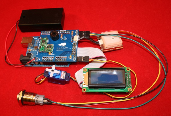
Completed assembly
Building your own box can be a very rewarding experience on a number of levels. Let’s look at what tools you’ll need.
[+]Tools
- Soldering iron, solder, and probably wick. There’s no two ways around it: you’re going to have to do a little bit of soldering in this project. But our Reverse Geocache™ Version 2 Shield Kit keeps this as simple as possible. There is no super-fine pitch soldering.
- Woodworking tools. You’ll need to be able to cut holes in your box for the display, the USB port, and the button to emerge.
- Epoxy glue. There is lots of gluing in this project.
Components
This is all you need to build the box:
- Arduino Uno R3 microcontroller – the basic brain behind the box
- Sundial Reverse Geocache™ Version 2 Shield Kit
- Sundial Reverse Geocache™ Box Kit
- GlobalSat EM-406A GPS module
Step 1: Solder the Reverse Geocache™ Version 2 Shield Kit
- Cut the 40-pin bank of male pins into groups of 8-8-6-6-1-1 (with 10 pins left over) using snippers. Place the Arduino on a table top, and insert 4 banks of straight header pins (8, 8, 6, 6) into the female header sockets, “long end down”.
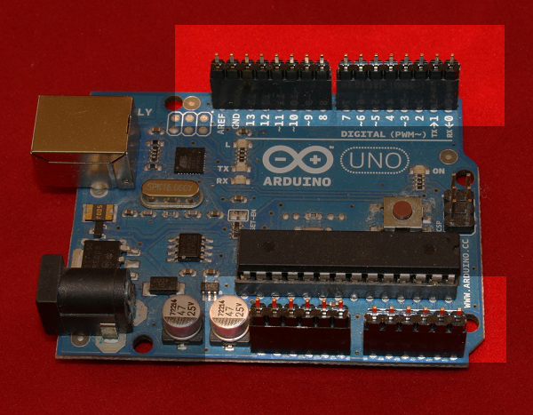
Arduino with Pins
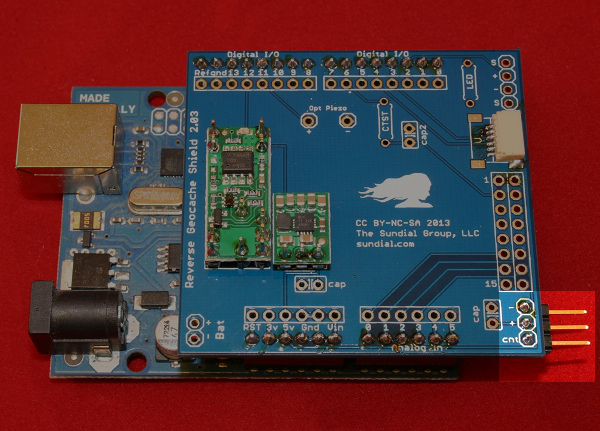
- Mate the shield to the tops of the pins, and solder the pins to the shield.
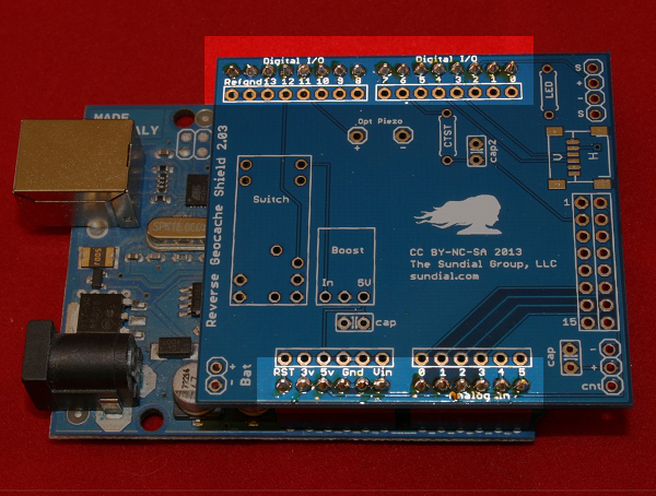
Shield with Soldered Pins
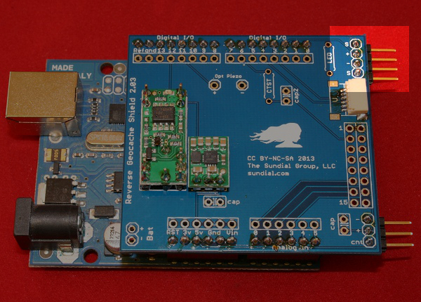
- Solder the tiny 6-pin GPS JST connector to its position at the edge of the shield. This is the trickiest part and may require some work with a wick to remove excess solder. Carefully solder each of the six pins, then make sure to solder the two “anchor” pads. (You’ll be sad if you forget to do this and your hard work goes to waste when you accidentally rip up the connector.) The easiest way to solder the connector pins is to start with a tiny dollop of solder on one of the pin pads. Set the connector down on top of it and remelt this blob to fasten the connector in place. Then carefully touch a bit of solder to each of the remaining 5 pins. Use solder wick if you bridge any of the connections.
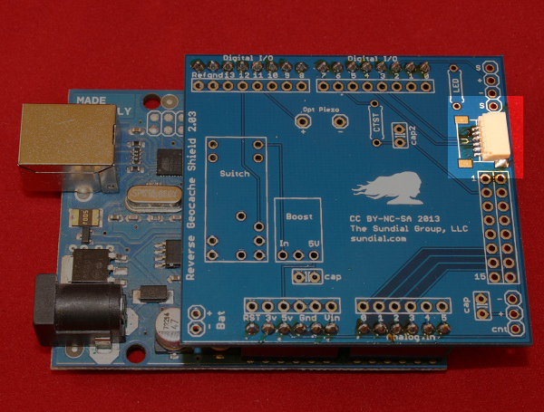
GPS Connector
- Solder the 11-pin Pololu switch module to the shield PCB using 11 straight header pins. Snip the provided 9-pin bank of male pins into groups of 2+2+2+3. You can discard the pushbutton that comes with the switch. (It is superfluous here.) Make sure the two button terminals in the middle of the switch module are soldered to the board using the two single pins you cut in the first step. First insert the 11 pins “short end down”:
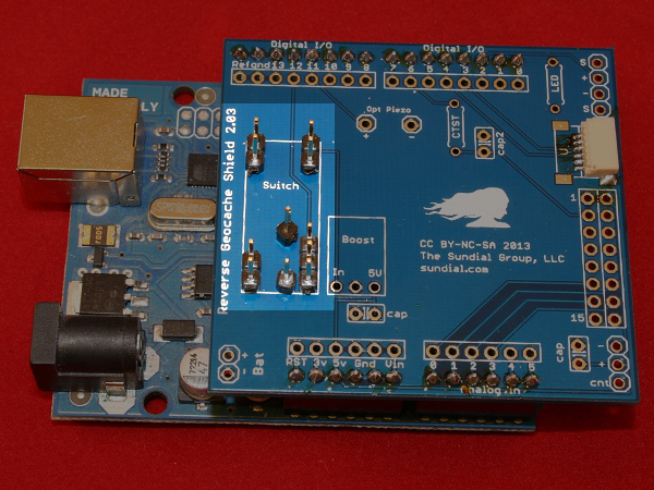
Switch Pins
- Then solder the long end of the pins to the switch module, and turn upside down and solder the short end to the shield PCB.
Switch Module
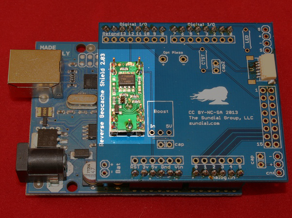
- Solder the 3-pin Pololu boost regulator module to the shield PCB using 3 straight header pins. You can discard the right-angle connector Pololu provides. First insert the three pins, again, small end down:
Boost Regulator Pins
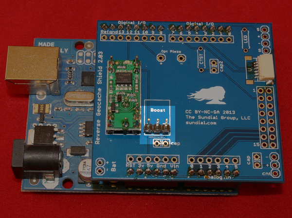
- Then the regulator board like this:
Boost Regulator
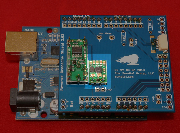
- Solder the 3-pin right-angle servo motor connector. This should extrude downward also to keep the assembly as thin as possible.
Servo Connector
- Solder a 4-pin straight (or angled) header for the button. This should extrude downward also.
Pushbutton Connector
- Solder 2×8-pin header for the display connector to the shield PCB. Note that the long pins extrude downward, so that the ribbon cable will connect to the underside of the shield.
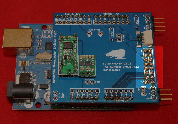
Display Connector
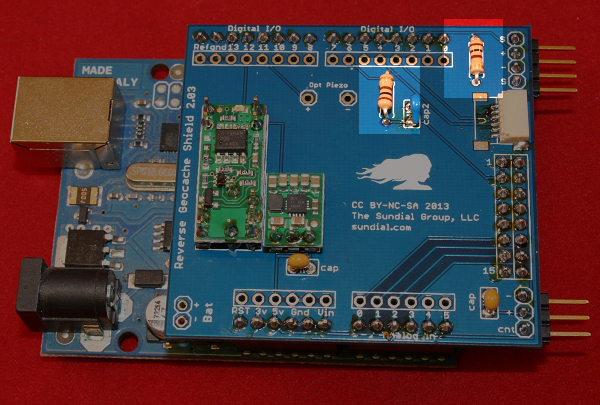
- Solder two 0.1 yellow microfarad smoothing caps to the spots on the shield marked “cap” and clip their legs. Similarly, solder the blue contrast circuit capacitor into the spot marked “cap2”. These capacitors don’t have an orientation, so you can solder them either way around. (The version 1.xx shields don’t have the blue contrast circuit capacitor.)
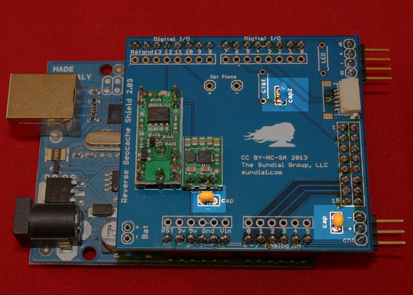
Capacitors
- Solder the two resistors to the shield in the appropriate spots and clip their legs. These are the LED current limiting resistor and the resistor for the display contrast circuit. Resistors don’t have an orientation, so you can put them either way around. (Note: there is only one resistor in the version 1 kits. These didn’t have a contrast circuit.)
Resistors
- (Version 2.xx only, optional) If you’d like to add some sound to your project, solder the piezo buzzer to the board to the spot marked “opt piezo”. Make sure you solder the leg marked + into the hole marked +. Clip the excess leg length.
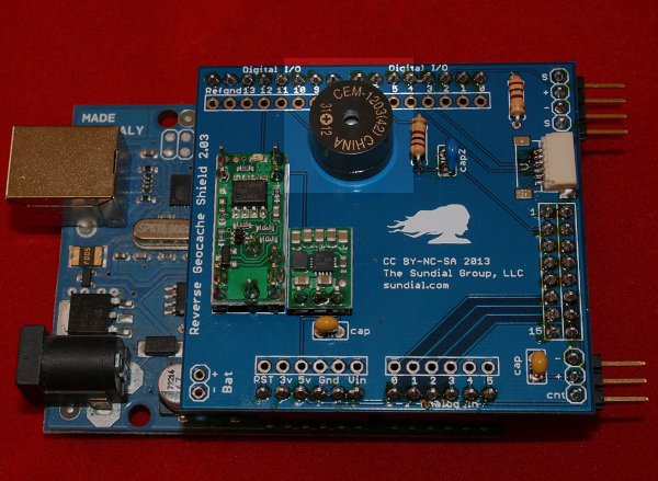
Buzzer
Step 2: Assemble the Reverse Geocache™ Box Kit
- Solder the battery holder terminals to the battery connector. The red (+) wire connects to the solder point marked “+” on the PCB. (These wires are fragile; try not to bend them.)
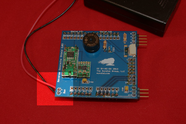
Battery Pack
- Look at the terminals on the button as a smiley-face. In this orientation, from left to right the connections are, #1 (LED+), #2 NO CONNECTION, #3 (SW1), #4 (SW2), #5 (LED-).
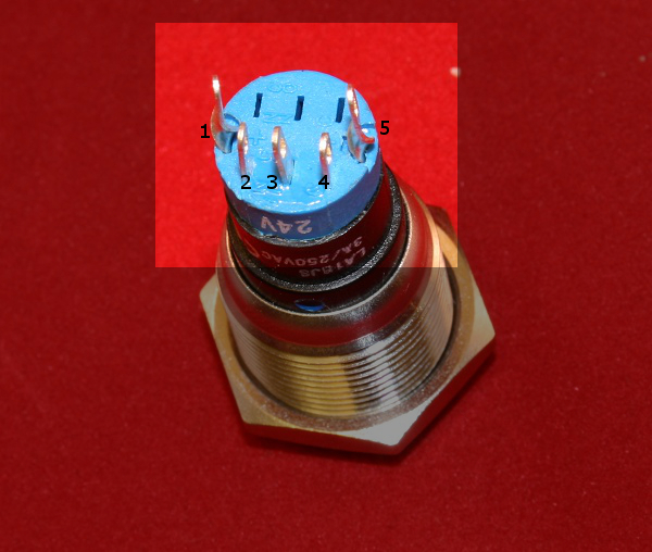
Pushbutton Pins
- Snip one end off the 4-pin cable and solder to button terminals. The cable will connect to the 4-pin header you soldered in step one. The LED+ terminal on the button should connect to the pin marked + on the shield.
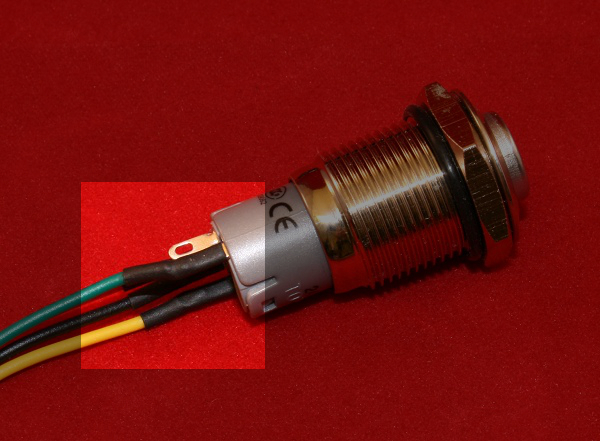
Wired Pushbutton
- Solder a 2×8 connector to the display.
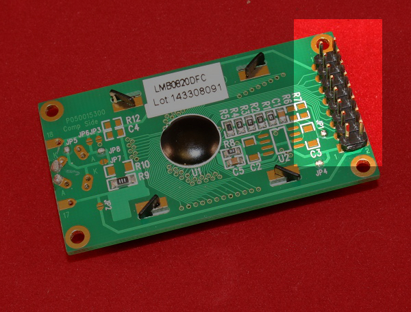
Display Pins
- Hook up the 2×8 display ribbon cable to the display at one end and the shield on the other. Make sure pin 1 matches on both ends. Connect the servo to the 3-pin connector. The yellow cable on the HS-55 is the “control” line. Make sure that matches the ctrl line on the PCB. Plug in the EM-406A GPS module and the pushbutton cble.
Completed assembly
Step 3: Assemble the latch
There are two variants of the pushrod mechanism that we’ve shipped with the box kits. One variant comes with a clevis and screw-in pushrod. The latter is a single rod with a “Z-bend” and is more commonly used in servo applications like RC airplanes. In both cases it will be necessary to drill out the tiny hole in the white servo arm, because the hole is not big enough to accommodate the width of the clevis (in the one case) or the rigid pushrod (in the other).
Here’s a picture showing a completed sample clevis assembly:

Completed assembly – before mounting.
Step 4: Modify and Upload the Software
In addition to the sample firmware, you’ll need the Arduino software and a couple of support libraries from Arduiniana: TinyGPS and PWMServo.
You’ll then need to customize the sample firmware to suite your particular box and quest. Look for the section in the code that looks like this, and change the values accordingly.
/* These values should be adjusted according to your needs */
static const int CLOSED_ANGLE = 90; // degrees
static const int OPEN_ANGLE = 165; // degrees
static const float DEST_LATITUDE = 48.8469;
static const float DEST_LONGITUDE = -2.9986;
static const int RADIUS = 2000; // meters
Step 5: Cut and assemble the box
- It has to have a rectangular hole to mount the small display behind.
- There needs to be a judiciously-placed hole for the Arduino’s USB port to extrude through the exterior wall so that the box can be configured.
- A 5/8″ circular hole needs to be drilled somewhere to accommodate the push button.
- There has to be room to mount the battery holder and the GPS module with glue or sticky tape.
- And of course the servo needs to be securely glued and the latch mechanism assembled.
Notes
Reverse Geocache™ and Quest Box™ are trademarks of The Sundial Group.
These instructions and the sample source code are licensed under the terms of the Creative Commons “Attribution Non-Commercial Share Alike” license, version 3.0, which grants the limited right to use or modify it NON-COMMERCIALLY, so long as appropriate credit is given, and derivative works are licensed under the identical terms. See here for license details.
The Sundial Quest Box and some of the technologies described here are patent pending.